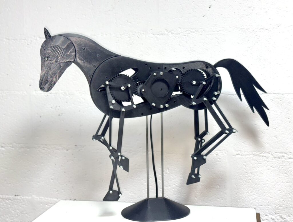
From the idea of an automaton in the shape of a horse to this:
A new chapter: automata
This site has always been about 3D-printed clocks. This year I started a new chapter: automata. My first one is a walking mechanical horse, and this is its build diary, from July 2026 to now.
Clocks are a solved problem, with centuries of recipes. A horse is not. It has to look like a horse and move like one, and those two goals fight inside a linkage. That is probably why there are thousands of clock files online and only a handful of mechanical horses.
While researching moving horses on YouTube, I noticed one horse that clearly stood out:
Horse made by François Junod, automaton maker in Sainte-Croix, Switzerland
Link to his horse video on YouTube
Licou, my linkage bench
I started by playing with a Theo Jansen leg in a small simulator, with a slider on every link. It taught me a lot, but a Jansen leg is a crab leg, not a horse leg. So I built my own tool.
This is the first part on relying heavily on AI to write some code. It was a back and forth for a few weeks, between Claude for brainstorming and Claude Code in the IDE to write the code.
I named it Licou: link plus coupler, and the French word for a halter. It is a standalone app that draws a linkage, animates it and traces the foot path. Its solver never flips into the mirror position, which was my main problem with large sketches in FreeCAD. A mechanism has one crank and one or more fixed pivots, and two dozen links run fine. I first named the links with letters, then switched to numbers to allow more links.
By late August, one leg of 18 to 20 links ran smoothly. Front and rear legs share the same design, mirrored, with slightly different dimensions. The horse is suspended, so it never has to balance.
Link to my link simulator on GitHub
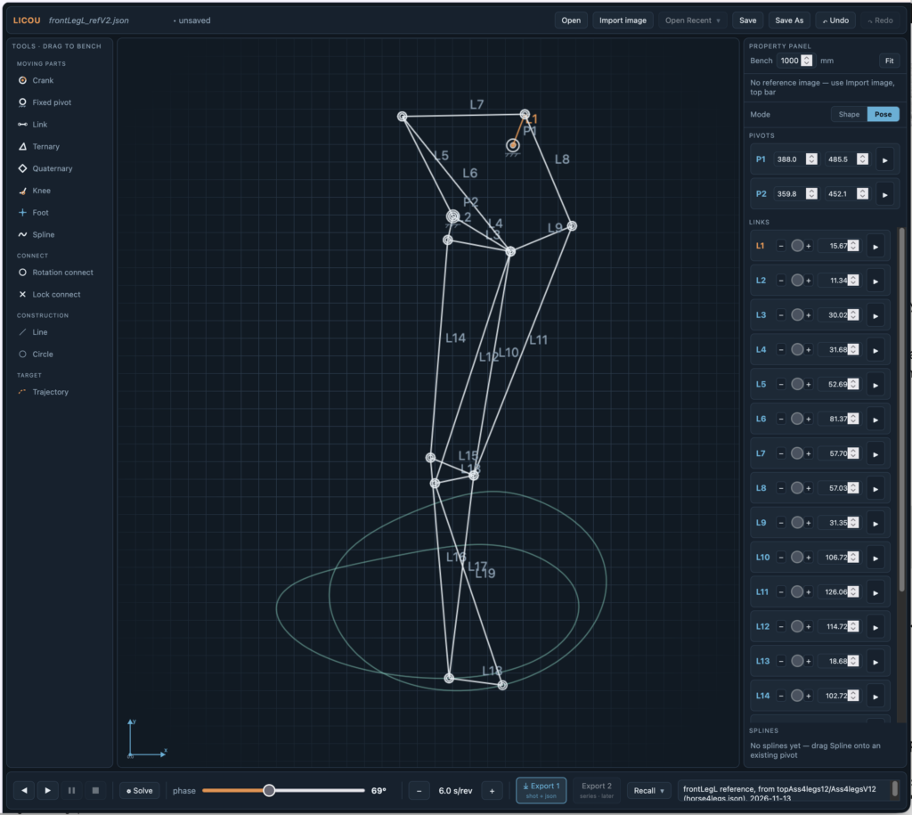
Licou Link Simulator
It is made on a Mac, runs in a browser, should work everywhere but is untested. Firefox and Chrome will allow multiple tabs at once.
Links can be adjusted incrementally with stepper in Pose mode, or dragged around in Shape mode. Files are saved as JSON files; they can be exported and reimported as needed.
Back and forth between Licou and FreeCAD
Licou designs the motion. FreeCAD builds the parts. Claude reads the FreeCAD file and writes JSON for Licou, and writes macros that push Licou’s changes back into FreeCAD.
Once I started designing the assembly, I realized that my legs were too big. I could ask Claude Code to write a macro to reduce all parts dimensions to two-thirds of the size, and replace all holes of 5 mm with 4 mm.
This saves me a lot of time editing files:
- FreeCAD to Licou. Once my four-leg assembly existed in FreeCAD, code read the file and built the four-leg view in Licou automatically, with each leg’s crank offset taken from my constraints.
- Licou to FreeCAD. When I redesigned a leg and changed dimensions on the Licou bench, a script took all the new dimensions and updated every leg in FreeCAD.
- Timing. I first set the leg offsets by hand. Licou then gave me more precise offset angles, which I put back into the FreeCAD assembly for better synchronised legs.
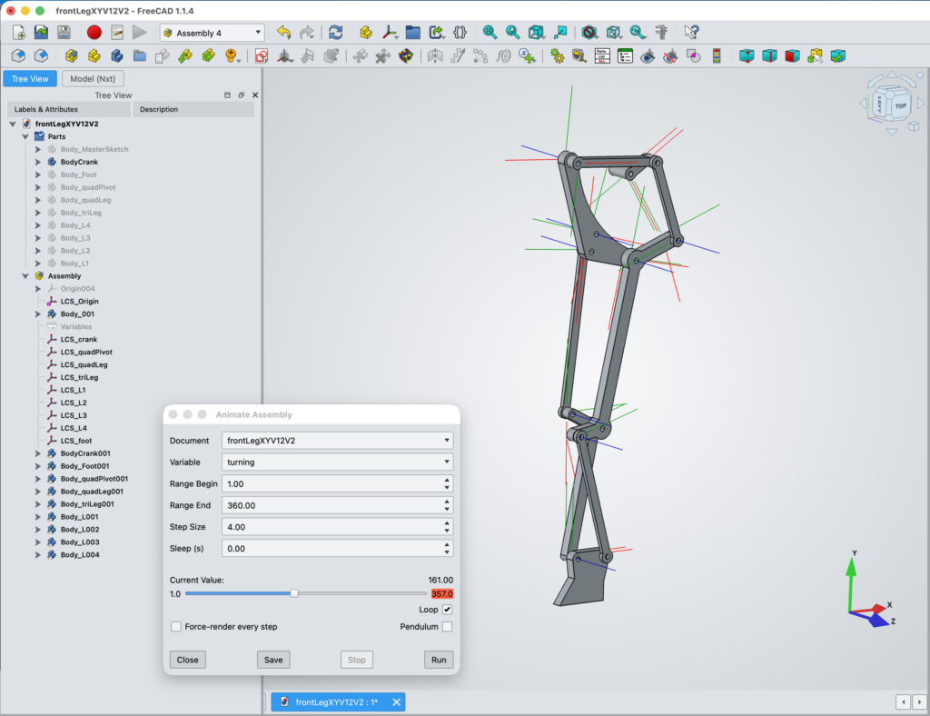
How the FreeCAD file is organised
This was quite a project, and as often, I did not have a clear picture of how it would end up.
At first I was not sure how FreeCAD could animate four moving legs. It can, with some care. I used Assembly 4 for all this.
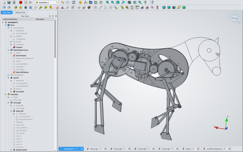
I first made an assembly of one leg. Once I learned how to make it work, I made an assembly of assemblies. FreeCAD keeps all the part links working, as long as all files live in the same folder.
The top assembly contains lots of moving parts, and sketches that are not fully constrained can behave in interesting ways.
- Four independent assemblies of legs: two front, two rear, each in its own file. Each leg carries its own crank, with a gear attached.
- Top assembly: where everything comes together, all 4 legs, and all the other parts
- Z-plates: a separate file holding the body, neck and head plates. It is named so it sorts last in the list.
- Motor mount plate, plus a STEP model of my motor, made by Claude from photos, so I could place it in the assembly.
- Gear train: a gear on the motor drives other gears that spread the motion to all four leg cranks.
- Head: a separate file, not yet in the assembly.
Tips I learned the hard way:
- One driving variable. The crank angle is defined in the top assembly first, then linked to each leg. One variable drives all four legs.
- LCS that don’t flip. To place a local coordinate system reliably, pick the vertex first, then two lines to define the plane.
- Keep the plates out of the assembly. I started building plates inside the top assembly. Little by little it grew into a big mess, and it took real work to clean up. Now the plates live in their own document, built from only three sketches and shapebinders. Claude recombined my many earlier sketches into these few, fully constrained.
- Start every plate from the horse outline. I first drew an outline sketch of the horse in the assembly, then used it as the base for the plates. Every plate shares the same origin, drawn well outside the assembly for clarity.
- New plates through the Assembly workbench. Starting a new plate there gives it an LCS origin automatically. Then I only adjust the Z offset to put it at the right depth.
- One sketch for all the holes. The most useful trick of all: a single sketch holds every bolt and pin hole for every plate. No measuring, no odd distances; the holes line up by construction.
- Hollow plates. One spline sketch hollows the plates to make room for the motor and gears.
The head
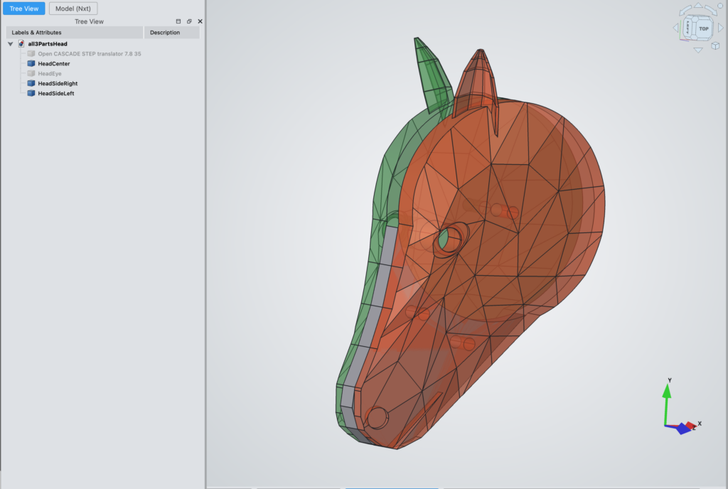
It started as a flat contour of the head. Then, from pictures of a toy horse and outline guides, I used Claude to generate a low-poly head. It has three parts: a central muzzle and two side plates, joined by pins so the head can rotate on the neck. It started as a script producing STEP and STL files, then became a macro that runs inside FreeCAD, so I can edit it there.
The drive
My long-term goal is a fully mechanical horse, driven by a kind of escapement system. For the sake of simplicity, the prototype runs on an electric DC motor. It works, but it is too noisy.
The next step is a stepper motor. That opens a bigger idea: one stepper per leg. The gait timing then lives in software, and the same horse could switch between walk, trot and canter.
What’s next
- Timing holes in every leg, so one pin locks all four at the same crank angle.
- A 3D tail.
- More body plates over the centre and the motor, so as few links as possible show.
- Replace the DC motor with a stepper, then maybe one stepper per leg.
- Add head and tail motion.
- Build a foal.
- Build other animals: deer, cows, dogs or big cats.